Exploring Cisco Network Address Translation ( NAT) - Part -I
Even though I worked with NAT configuration it still troublesome when configuring NAT on the Cisco Router (I prefer the Mikrotik way of configuration, simple but powerful).
First in the Cisco NAT world we have to understand these 4 terms. Directly taken from Cisco [1]

First in the Cisco NAT world we have to understand these 4 terms. Directly taken from Cisco [1]
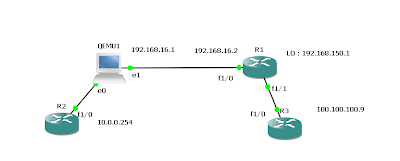
• Inside local address—The IP address assigned to a host on the inside network. This is the address configured as a parameter of the computer OS or received via dynamic address allocation protocols such as DHCP. The address is likely not a legitimate IP address assigned by the Network Information Center (NIC) or service provider.Following diagram depicts the terms in the actual traffic flow.
• Inside global address—A legitimate IP address assigned by the NIC or service provider that represents one or more inside local IP addresses to the outside world.
• Outside local address—The IP address of an outside host as it appears to the inside network. Not necessarily a legitimate address, it is allocated from an address space routable on the inside.
• Outside global address—The IP address assigned to a host on the outside network by the host owner. The address is allocated from a globally routable address or network space.

Following as depicted host1 and host 2 in the range if 192.168.100.0/24 range and 192.168.100.1 as the virtual ip for the HSRP group 10.
Simulated Inside network doesn’t have access to outside without natting.

R2#ping 192.168.100.1
Type escape sequence to abort.
Sending 5, 100-byte ICMP Echos to 192.168.100.1, timeout is 2 seconds:
...
Success rate is 0 percent (0/3)
Type escape sequence to abort.
Sending 5, 100-byte ICMP Echos to 192.168.100.1, timeout is 2 seconds:
...
Success rate is 0 percent (0/3)
First lets see what the options available for ip nat : (7200 Software (C7200-ADVENTERPRISEK9-M),
R1(config)#ip nat ?
Stateful           Stateful NAT configuration commands
create             Create flow entries
inside             Inside address translation
log                NAT Logging
outside            Outside address translation
piggyback-support  NAT Piggybacking Support
pool               Define pool of addresses
portmap            Define portmap of portranges
service            Special translation for application using non-standard port
sip-sbc            SIP Session Border Controller commands
source             Source address translation
translation        NAT translation entry configuration
1) stateful nat (SNAT) works with HSRP/or independently to smooth tcp transition when the active/primary router fails [2]. this feature simply sync the flow entries to other router udp it uses port 15555.
first HSRP configuration on the R1#
R1#
interface FastEthernet1/0
ip address 192.168.100.2 255.255.255.0
ip nat inside
ip virtual-reassembly
duplex auto
speed auto
standby 10 ip 192.168.100.1
standby 10 priority 110
standby 10 name snat_hsrp
second we have to create ip nat stateful configuration .
ip nat Stateful id 10 #id should be unique for each router
redundancy snat_hsrp // identify the hsrp group
mapping-id 100 // this id will be mapped with nat
protocol   udp // we can use either tcp or tcp
Then we have to create the NAT pool :
ip nat pool TEST2 117.117.117.1 117.117.117.1 netmask 255.255.255.0
ip nat inside source list 105 pool TEST2 mapping-id 100 overload
// check the mapping id is matched here..
same as R8 configured
R8#show run int fa2/0
Building configuration...

Current configuration : 192 bytes
!
interface FastEthernet2/0
ip address 192.168.100.3 255.255.255.0
ip nat inside
ip virtual-reassembly
duplex auto
speed auto
standby 10 ip 192.168.100.1
standby 10 name snat_hsrp
// stateful configuration.


ip nat Stateful id 20 // id is different
redundancy snat_hsrp
mapping-id 100
protocol   udp
ip nat pool TEST2 117.117.117.1 117.117.117.1 prefix-length 24
ip nat inside source list 105 pool TEST2 mapping-id 100 overload
according to this configuration, if stateful nat is not configured only the R1 should have the natting flow entries ( HSRP priority 110). but if you check the R8 nat table same entries kept on R8.
R8#show ip nat translations
Pro Inside global      Inside local       Outside local      Outside global
tcp 117.117.117.1:55833 192.168.100.100:55833 116.116.116.5:22 116.116.116.5:22
tcp 117.117.117.1:55834 192.168.100.100:55834 116.116.116.5:22 116.116.116.5:22
[2] “Scalability for Stateful NAT - Cisco Systems.” [Online]. Available: http://www.cisco.com/en/US/docs/ios/12_4/12_4_mainline/snatsca.html. [Accessed: 15-Apr-2011].


Comments